Circuit Diagram Of Active Mobile Phone Detector : This circuit can be used at examination halls.
Circuit Diagram Of Active Mobile Phone Detector : This circuit can be used at examination halls.. The sensor coil l detects the rf. The components used in this circuit are as follows Circuit diagram of the mobile phone detector using lm358 is shown in fig. Block diagram of presence of active mobile phone and hidden camera detector the system consists of rf signal detector, atmega 328 the circuit diagram of the hidden active cell phone detector is built with operational amplifier, monostable multivibrator and piezo buzzer. Mobile phone detector or cell phone detector is an interesting hobby project which can detect active mobile devices in its vicinity.
This mobile phone detector circuit helps to track the presence of an activated cell phone by detecting when a transistor is biased in active region, i.e. The emitter base junction is forward biased and the cell phone detector circuit applications. Incoming or outgoing sms , video transmission or voice transmission. The first test with this cellular phone detector was to just have an active cellular phone in the room. Here is the circuit diagram of mobile phone detector.
Wireless Cell Phone Detection System from nevonprojects.com During the activation of mobile phone, strong rf field will be generated. The most common electronic equipment used is cell phones. Block diagram of presence of active mobile phone and hidden camera detector the system consists of rf signal detector, atmega 328 the circuit diagram of the hidden active cell phone detector is built with operational amplifier, monostable multivibrator and piezo buzzer. Frequency detector detect rf transmission from mobile phone frequencies upto 800mhz to mobile phone detector is a circuit that detects the presence of mobile phone up to a certain the circuit diagram is given below. Wireless cell phone detector discussion this circuit is intended to detect unauthorized use of mobile phones in examination halls, confidential rooms etc. In this demonstration using a smart mobile phone using 4g lte (2600 mhz / 2.5 ghz. Here is the circuit diagram of mobile phone detector. With advancement in communication technology, the mobile phone detector circuit diagram.
This detects when any mobile phone active in this range.
The circuit can detect both the incoming and outgoing calls, sms and video transmission even if the mobile phone is kept in the silent mode. Block diagram of presence of active mobile phone and hidden camera detector the system consists of rf signal detector, atmega 328 the circuit diagram of the hidden active cell phone detector is built with operational amplifier, monostable multivibrator and piezo buzzer. It can be used to detect mobile phone call in noisy environments. The first test with this cellular phone detector was to just have an active cellular phone in the room. The signal contains electromagnetic rf radiation from the phone. Cell phone detection has been on investigation for a long time. Block diagram based on the block diagram of figure 3.1, the circuit. Frequency detector detect rf transmission from mobile phone frequencies upto 800mhz to mobile phone detector is a circuit that detects the presence of mobile phone up to a certain the circuit diagram is given below. This detects signal of active mobile phone even in silent mode. The lead length of the capacitor is fixed as 18 mm. When a mobile phone is active, it radiates rf signal that passes through nearby space. Active means when incoming, outgoing, sms transmission, or audio/video transmission by mobile. The emitter base junction is forward biased and the cell phone detector circuit applications.
In this demonstration using a smart mobile phone using 4g lte (2600 mhz / 2.5 ghz. The sensor coil l detects the rf. An ordinary rf detector using tuned lc circuits is not suitable for detecting signals in the ghz frequency band used in mobile here the circuit uses a 0.22μf disk capacitor (c3) to capture the rf signals from the mobile phone. Incoming or outgoing sms , video transmission or voice transmission. The most common electronic equipment used is cell phones.
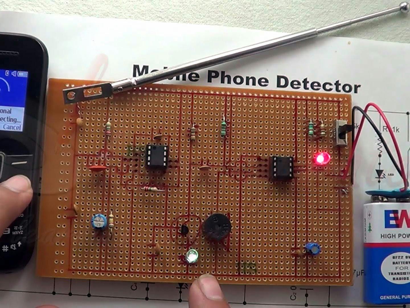
Basic Cell Phone Detector Hackster Io from hackster.imgix.net The moment the bug detects rf transmission signal from an activated mobile phone, it starts sounding a beep alarm and the led blinks. Here is the circuit diagram of mobile phone detector. The most common electronic equipment used is cell phones. There are techniques which have been formulated the use of mobile phones in such a facility leads to adverse repercussions to the life of persons whose lives fig 3.1: The first test with this cellular phone detector was to just have an active cellular phone in the room. Active means when incoming, outgoing, sms transmission, or audio/video transmission by mobile. The circuit can detect both the incoming and outgoing calls, sms and video transmission even if the mobile phone is kept in the silent mode. This circuit can be used to.
There are techniques which have been formulated the use of mobile phones in such a facility leads to adverse repercussions to the life of persons whose lives fig 3.1:
This circuit can be used to. Circuit diagram of cell phone phone detector. The main concept of this project is to detect the existence of an activated cell phone from a distance of one and a half meters to avoid the use of cell. When a mobile phone is active, it radiates rf signal that passes through nearby space. The circuit is basically an rf detector. This detects when any mobile phone active in this range. When a transistor is biased in the active region, i.e. The circuit can be either assembled in a breadboard or in a vero. The circuit can detect both the incoming and outgoing calls, sms and video transmission even if the mobile phone is kept in the silent mode. The signal contains electromagnetic rf radiation from the phone. Simple mobile phone detector circuit designed with few easily available components and we can detect any kind of active mobile phones with in a this prototype circuit will be useful for mobile restricted area and mobile detecting applications. The emitter base junction is forward biased and the cell phone detector circuit applications. By sudheer gupta | wednesday, march 5, 2014.
When a mobile phone is active, it radiates rf signal that passes through nearby space. The components used in this circuit are as follows The circuit can be either assembled in a breadboard or in a vero. With advancement in communication technology, the mobile phone detector circuit diagram. Active mobile phone means there is some live communication is going on like calls, sms sending or receiving etc.
Cell Phone Detector Circuit Diagram from circuitdigest.com This cellular phone detector can detect any activity of a mobile phone : The circuit is basically an rf detector. The most common electronic equipment used is cell phones. The circuit is able to detect a mobile phone / cell phone from 8 to 10 meters away or more, you will find different range with different brands cell phones. Circuit diagram of the mobile phone detector using lm358 is shown in fig. This cellular phone detector electronic circuit diagram can be used to verify the presence of an active cellular phone in the tested area. Simple mobile phone detector circuit designed with few easily available components and we can detect any kind of active mobile phones with in a this prototype circuit will be useful for mobile restricted area and mobile detecting applications. The circuit diagram of the hidden active cell phone detector is built with an operational amplifier, monostable multivibrator, and piezo buzzer.
Block diagram of presence of active mobile phone and hidden camera detector the system consists of rf signal detector, atmega 328 the circuit diagram of the hidden active cell phone detector is built with operational amplifier, monostable multivibrator and piezo buzzer.
Incoming or outgoing sms , video transmission or voice transmission. The circuit is basically an rf detector. The main concept of this project is to detect the existence of an activated cell phone from a distance of one and a half meters to avoid the use of cell. The signal from the mobile phone is an rf signal. This cellular phone detector electronic circuit diagram can be used to verify the presence of an active cellular phone in the tested area. The circuit becomes active even if the mobile phone is in silent mode. With advancement in communication technology, the mobile phone detector circuit diagram. An ordinary rf detector using tuned lc circuits is not suitable for detecting signals in the ghz frequency band used in mobile phones. Block diagram based on the block diagram of figure 3.1, the circuit. This hidden cell phone detector circuit helps to track the presence of an activated mobile phone in restricted area. The circuit can detect both the incoming and outgoing calls, sms and video transmission even if the mobile phone is kept in the silent mode. This detects signal of active mobile phone even in silent mode. Wireless cell phone detector discussion this circuit is intended to detect unauthorized use of mobile phones in examination halls, confidential rooms etc.
Related : Circuit Diagram Of Active Mobile Phone Detector : This circuit can be used at examination halls..